Monday, November 30, 2015

Lab 13: Reflections and Mirrors


Lab 13: Reflections and Mirrors

In lab 13 we experimented mirrors to see how they reflect images and how reflection truly works. Reflections are based on how light reflects off of the reflective surface of a mirror. This causes the light to then be bounced equal arc of which some will bounce into a human eye to be perceived and viewed. This equal arc also causes the light to occupy a fixed point, and based on the mirrors position causes how we can move into and out of view of the mirror. Throughout our experiments we found that these points will be fixed and will perceive the same amount of the person no matter how far away the person is from the mirror, if it can’t see your legs at 5 ft away, it can’t see them 10-15- or even 20 ft away. As a result we were asked, what is the minimum size we can have in a mirror for it to be able to see our entire body and reflect it back at us.

To figure this out we realized that the point on the mirror that we needed to adjust was the midpoint, the area where the light bounced off of the mirror and back at us. We calculated that since the angle was always the same we could use a midpoint on our own body’s dimensions to figure out how to calculate the size. Because the rays always had to reflect to our eyes, we measured the distance from our toes to our eyes, from our shoulders to the opposite eye, and from the top of our heads to our eyes. I am personally 6'4 and had the following calculations, 182 cm toe to eyes, 8 cm top of head to eyes, and roughly 40 cm shoulder to opposite eye. We then halved this data to use their midpoint, and then added the measurements that would be used to find the mirrors dimensions, namely the head and toe points for height, and the shoulder points for width. After computing this i found that for a mirror to be properly sized for me it would need to be 95 cm tall and 40 cm wide.


Errors
As usual we did have plenty of opportunities for error. One major problem we could have had is problems measuring and rounding, as all we had was a yard stick that had to be flipped and remeasured to measure our overall height. We also had problems rounding and would commonly round to the nearest centimeter for easy use, which could provide some problems given that the dimensions needed to be exact, but a few millimeters will not make a noticeable or major difference.

Friday, November 20, 2015

Lab 12: Mechanical Waves

Lab 12: Mechanical Waves

For lab 12 we experimented with waves, specifically the mechanical waves generated by pulses. To do this we hooked a frequency generator and a mechanical wave oscillator to a string and pulled the string taunt to monitor how the frequency of the generator affected how many nodes and anti-nodes were generated. To summarize, a node is a point where the two differing waves cancel each other out and seem to have no displacement, while an anti-node is maximum point of the wave’s generated path. These points are then used to calculate the wavelength of the wave, allowing it to be measured and predicted.
 
We were tasked with finding if there was a relationship between the Node Node and Node Anti node patterns and finding out if they act the same way as the transverse standing waves? a Node Node pattern is when the wave on the string begins and ends on a node, while a Node Anti node pattern is when it starts or ends with an Anti-node and ends with the opposite. we first experimented with the transverse wave, noting the wavelength of the wave as the hertz was increased. our data was as follows.


This data showed us that the nodes and wavelengths increased as time went off, with a few outlier's until we hit 32 hertz where the total wavelengths dropped and then began to increase again. 

We then repeated the experiment with a spring instead of a rope to better measure the node patterns in them with more accuracy. We found that the nodes pattern would alternate every 5 hertz increase. As we experimented higher and higher we noticed that the number of nodes and anti-nodes would increase, this gives us the impression that the two systems are very similarity, which makes sense as they rely on the same drivers and functionality. 


Problems:
There were a few margins for error in our experiments that need to be accounted for. Firstly our equipment had occasional problems achieving the correct speed, leading to some puzzling readings which are why we do not have any data pictures for the second part. Additionally we have the traditional human error problems for input, and may have added in unknown outside problems due to treatment of the machines or how they were placed.


Friday, November 13, 2015

Lab 11: Electromagnetic Induction

 For lab 11 we experimented with electromagnetic induction using a Magnet, coils with varying number of windings, a galvanometer, a power supply, and connecting wires. We were tasked with influencing the magnitude of the inducting current, shown on the galvanometer. To do this we first experimented by hooking a magnetic coil to a galvanometer and ran a magnet through the coil, alternating its sides and monitoring the galvanometer. We found that running the magnets through the coil would cause the galvanometer to register an increase when the north side was run through the coil and a decrease when it left, while the opposite was true when the south side went through it. This was due to the magnetic field that the magnet possessed, which changed to the coils electric current causing the changes.


Next we experimented with the voltage of the coil. We hooked a power supply to the coil and experimented with changing the voltage run through the coil. We found that increase the voltage decreased the current, and again the inverse caused it to increase. This was caused due to the coils current working to compensate and equalize for the voltage to equalize its magnetic field.


Next we experimented with a second coil, we added a second coil to the first and linked the two but did not link the second to the power supply. This caused the reverse effect of the previous experiment, with the second coil equalizing the first and thus causing it to increase its magnetic field to compensate.


Finally we repeated the previous experiment but with a magnet, in this occasion we found that the second coil had the reverse reaction to the first, noting that it’s current would increase with the south side of the magnet and decrease with the north.


from these experiments we were able to note that many things increase the coils magnetic field, the facing of a magnet that is brought into it, reducing the voltage introduced to the coil, and the introduction of a second coil that will experience a reverse version of all of the different ways that we attempt to influence the magnetic field with. Thus there are a large amount of things that can influence a coils magnetic field, and in many ways.

Friday, November 6, 2015

Lab 10: Magnetism

Lab 10: Magnetism

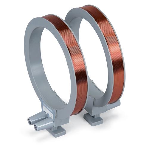
In Lab 10 we experimented with magnetic fields, studying how they acted and where they were directed between a magnets north and South Pole. During this experiment we measured our first 3 dimensional object that was large enough to interact with, a Helmholtz coil.
   
We were tasked with measuring it’s magnetic field lines to find where they went and isolate its north and south poles. to do this we took a compass and a sheet of paper to track the needles direction and began moving the compass in differing areas of the coil, marking the needles facing on the sheet of paper every roughly 30 degrees. Doing this we noticed that the field seems to move as shown below.

This showed us the main movement and area of the coils magnetic fields, and how similar they could be. The coil has a single moving line going through its center as a result of the cancelling effects of the different fields on either side of the center, creating a uniform and regular magnetic field that can be easily modified.

Possible flaws
due to our only measuring every 30 degrees we could have possibility missed or failed to gain the fields size due to measurement or user error, additionally as we could not directly trace it very well on the sheet of paper we were unable to guarantee that it was correct, a better way to possibly perform this experiment in the future would be with metallic dust that we could track and monitor to see how it moved in relation with the magnetic fields, but that could end up being too much of a mess to clean up to be worth using.